Electronics Jig | I/O Module

CAN-ControlledIntelligent Signal Interface

The TestBot IO Module bridges embedded systems under test with precise digital, analog, and PWM signal control-all commanded over CAN bus from within the same TestBot automation sequence.

TestBot IO Module
8+8
Digital I/O channels
0-3.3V / 0-5V
Analog output range
1 Hz-100 kHz
PWM frequency range
CAN
Host interface

What is a signal interface module - and why does embedded testing need one?

Embedded controllers-automotive ECUs, industrial PLCs, motor drivers, and IoT gateways-expose and consume a mix of digital GPIOs, analog voltage outputs, and PWM signals. Validating how firmware responds to these signals ordinarily requires a bench wired up with function generators, DACs, relay boards, and oscilloscopes. The IO Module consolidates this into a single CAN-addressed unit so teams can command and observe every signal type from inside a TestBot sequence, without manual rewiring between test cases.

TestBot IO Module front panel
Direct Answer

What the TestBot IO Module does

The TestBot IO Module is a CAN-controlled multi-signal jig for embedded hardware and ECU bench testing. It drives and reads digital outputs and inputs, generates analog voltages, and produces configurable PWM waveforms-all through a DBC-driven CAN interface that integrates directly with TestBot automation sequences.

Engineers command signal states or patterns from TestBot scripts, observe DUT responses, and generate timestamped pass/fail reports alongside other CAN, UDS, BLE, and WiFi test steps in the same run.

Digital input and output

Drive GPIOs high or low and read back logic levels to validate interrupt handling, enable pins, and status lines.

Analog voltage output

Command precise voltages across configurable ranges to stimulate ADC inputs, reference pins, and voltage-monitored rails.

PWM generation

Produce configurable frequency and duty-cycle waveforms to exercise motor drivers, fan controllers, and PWM-decoded sensors.

CAN DBC integration

Import a DBC file to map signal names to IO channels-no manual ID entry. Signals are addressable by name in TestBot sequences.

Why teams choose the TestBot IO Module

General-purpose DAQ and relay boards are designed for measurement, not for automation-native signal injection. The IO Module is bench-native: CAN-connected, DBC-driven, and built around real ECU signal validation workflows. It eliminates the separate function generator and relay board from the bench and replaces manual GPIO state toggling with repeatable scripted sequences.

Book a Demo

Digital I/O channels

8 independent digital outputs and 8 digital inputs support logic-level validation across enable pins, status lines, and interrupt inputs.

Analog stimulus control

Generate precise voltages to exercise ADC inputs, reference pins, and voltage-monitored rails with selectable 0–3.3V or 0–5V ranges.

PWM waveform generation

Create frequency- and duty-cycle-based profiles to validate motor drivers, fans, and PWM-decoded sensor inputs with deterministic timing.

Real-time signal monitoring

Read input states and analog levels at runtime so TestBot sequences can branch on DUT responses within the same test step.

Native TestBot reporting

Every signal command and observed state is logged with timestamps in HTML, PDF, and Excel test reports automatically.

Technical Specifications

Full electrical, interface, and operating characteristics for bench integration.

Signal, interface, and operating details for embedded validation.

SpecificationValue
Digital output channels8 independent channels, push-pull or open-drain
Digital input channels8 independent channels with configurable pull-up/pull-down
Digital logic levels3.3V and 5V selectable per channel bank
Analog output channels4 channels, 12-bit DAC resolution
Analog output range0–3.3V or 0–5V selectable per channel
Analog output accuracy±5 mV across full range at 25°C
PWM channels4 independent channels
PWM frequency range1 Hz to 100 kHz
PWM duty cycle resolution0.1% steps
Host interfaceCAN bus via DB-9 connector
Supported baud rates125 Kbps / 250 Kbps / 500 Kbps / 1 Mbps
CAN configurationDBC file with configurable ID and baud rate
Operating modesManual keypad mode / CAN-controlled remote mode
Signal update latency≤50 ms from CAN command to stable output
DisplayGraphical LCD, minimum 4 lines
Keypad5-key navigation pad
Power supplyExternal 12V DC adapter included
ControllerNXP LPC55S16, ARM Cortex-M33
Operating temperature0°C to +50°C
EnclosureIP40 rated with reinforced corner guards
Roadmap focus for v2: USB support, dual independent 16-channel banks, and analog input (ADC) readback channels.
Use Cases

What you can test with the TestBot IO Module

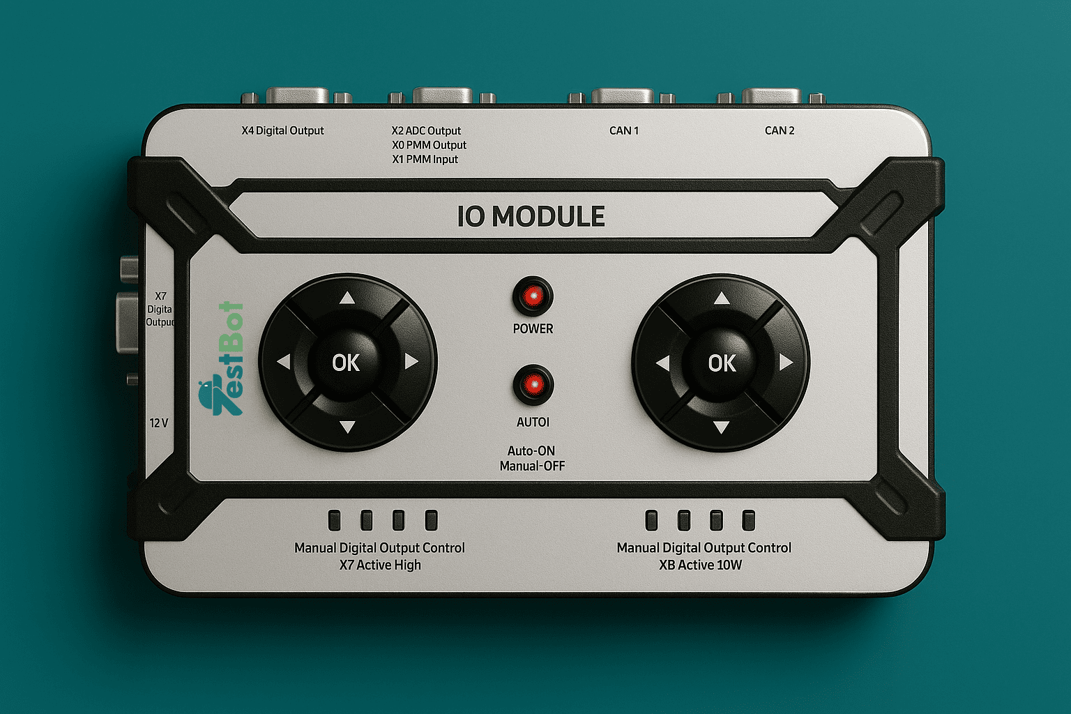
From GPIO validation and analog input stimulation to overnight regression runs, the IO Module replaces manual bench wiring with repeatable scripted signal sequences.

Digital I/O validation

Validate GPIO behaviour, interrupt handling, enable pins, and status line readback with repeatable high/low transitions.

  • GPIO interrupt handling
  • Enable and reset pin sequences
  • Status and fault line readback
  • Multi-step pin state patterns

Analog stimulus testing

Sweep ADC inputs, verify reference voltages, and emulate analog sensor behaviour without swapping external bench instruments.

  • ADC input sweep and calibration
  • Reference voltage validation
  • Analog sensor simulation
  • Rail voltage tolerance checks

PWM interface testing

Exercise motor drivers, fan controllers, and PWM-decoded sensors with controllable frequency and duty-cycle profiles.

  • Fan and motor driver stimulus
  • PWM-decoded sensor simulation
  • Duty cycle boundary conditions
  • Frequency sweep and lock tests

Automated regression testing

Run multi-signal scenarios overnight and capture every signal step, DUT response, and result in TestBot reports.

  • CI/CD-triggered firmware regression
  • Multi-signal scenario coverage
  • Overnight unattended runs
  • Audit-ready timestamped evidence
Integration

How the IO Module fits inside a TestBot automated test sequence

Steps

1

Configure Import the DBC file and assign digital, analog, and PWM signals to IO channels in the IO Agent. Set logic levels, voltage ranges, and PWM parameters per channel.

2

Execute Run IO Module command blocks inside the same TestBot sequence as CAN, UDS, BLE, WiFi, or DRB steps. Drive outputs and read back inputs in a single coordinated flow.

3

Report Every signal command, observed state, and timestamp is captured automatically. Export HTML, PDF, or Excel reports with step-level signal data and pass/fail results.

Book a Demo
Comparison

IO Module vs other signal interface solutions

The IO Module is positioned for embedded benches that need CAN-native multi-signal control and direct automation-framework integration-without building custom FPGA or DAQ rigs.

FeatureTestBot IO ModuleNI DAQ (USB-6001)Relay / GPIO boardFPGA dev board
CAN bus interfaceNativeNoNoCustom
Digital I/O8+8 ch
Analog output4 ch DACNo
PWM generation4 chLimitedNo
Standalone operationLCD + keypadNoNoNo
DBC-driven configYesNoNoNo
Test automation integrationNative TestBotCustom driverCustom scriptCustom HDL
Automotive-native workflowCAN DBCNoNoNo
Entry price$420~$200–$400~$30–$150~$200–$1,000+

Simple, transparent pricing

Hardware is purchased once. The IO Agent licence is renewed annually per station. Teams that already own a CAN adapter can add the IO Module without rebuilding the bench.

Frequently Asked Questions

Answers to the questions teams usually ask before adding the IO Module to an embedded hardware bench.

TestBot IO Module product image

The IO Module manages three signal types from a single unit: digital outputs and inputs (3.3V/5V), analog voltage outputs (12-bit DAC, 0–5V), and PWM outputs (1 Hz to 100 kHz with 0.1% duty cycle resolution).

Ready to automate multi-signal embedded testing?

Replace manual GPIO toggling, function generators, and relay boards with CAN-controlled digital, analog, and PWM sequences that report automatically in TestBot.