Modbus Exception Codes 01–04: What Each One Means and How to Write a Test for It
Most Modbus test suites validate the happy path: read a register, get the expected value, pass. What they miss is boundary validation - sending requests that should fail and verifying that the device fails correctly. A Modbus slave that returns exception code 02 for an invalid address is working correctly. A slave that returns nothing, or returns a positive response, has a defect.
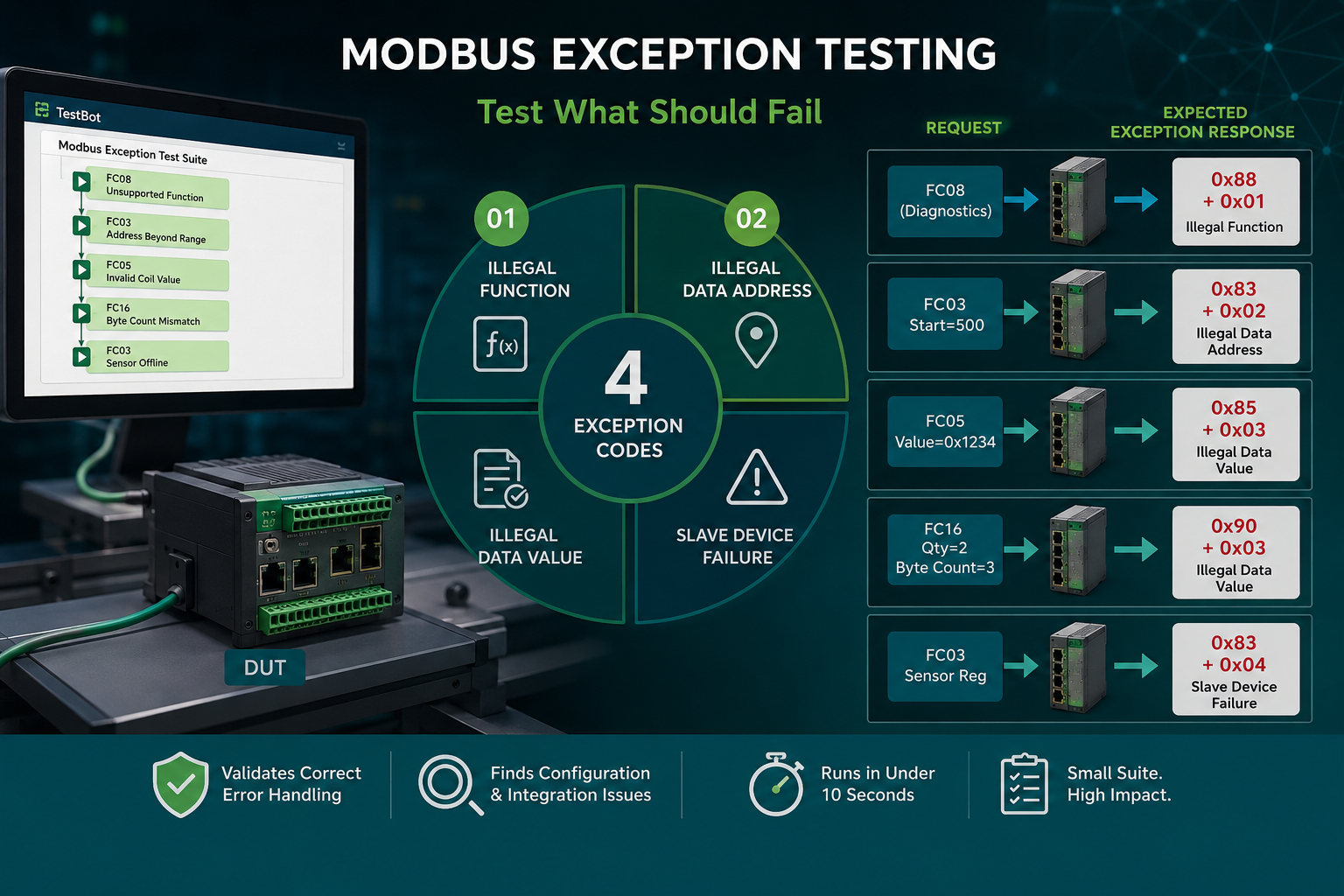
Modbus defines four standard exception codes. Each maps to a specific error condition that your test suite should deliberately trigger and verify.
Exception Code 01 - Illegal Function
Meaning: The function code in the request is not supported by this slave. The slave received the request correctly, understood the framing, but does not implement that function.
When it occurs: Your PLC or HMI sends function code 0x08 (Diagnostic) to a device that only supports FC01–FC06, FC15, FC16. Or a legacy device that does not support FC23 (Read/Write Multiple Registers).
Test case: Send a request with a function code the device is documented not to support - typically FC08 (Diagnostics) or FC20 (Read File Record). Assert the response contains 0x80+FC (e.g. 0x88 for FC08) in the function code byte, followed by exception code 0x01.
Why it matters: A slave that silently ignores unsupported function codes (no response) causes a Modbus master to retry and eventually timeout. Correct behaviour is to respond with the exception immediately. The master then knows why the request failed and can handle it.
Exception Code 02 - Illegal Data Address
Meaning: The data address in the request is outside the valid range for this slave. The slave supports the function code but does not have registers or coils at the requested address.
When it occurs: The master requests holding registers starting at address 1000 but the slave only has registers 0–499. Or the master requests a coil at address 200 in a device with only 64 coils (addresses 0–63).
Test case: For each data object type (coils, discrete inputs, holding registers, input registers), send a read or write request starting one address beyond the last valid address. Assert exception code 02. Also test the boundary exactly - the last valid address should succeed, one past it should fail.
Why it matters: This is the most common misconfiguration in fieldbus systems. A PLC configured with the wrong register map will get exception 02 responses. The slave that returns exception 02 is correct - the PLC configuration is wrong. Verify your device enforces its own documented address range.
Exception Code 03 - Illegal Data Value
Meaning: The data value in the request is not acceptable - it is outside the allowed range or format for that register or coil. The address is valid, but the value is not.
When it occurs: FC16 (Write Multiple Registers) with a byte count that does not match twice the register count. FC05 (Write Single Coil) with a value other than 0xFF00 (ON) or 0x0000 (OFF). A write to a register that only accepts values 0–100 with a value of 200.
Test cases:
- FC05 with a coil value of 0x1234 (not 0xFF00 or 0x0000) → exception 03
- FC16 with byte count = 3 for 2 registers (should be 4) → exception 03
- FC16 write to a range-constrained register (e.g. setpoint register 0–100) with value 101 → exception 03 (if the device validates range)
Note on range validation: Exception 03 for out-of-range values is device-specific. The Modbus specification does not mandate that devices validate application-level value ranges - only protocol-level format correctness. Some devices return exception 03 for out-of-range values; others accept the write silently. Document which behaviour your device implements and test for it explicitly.
Exception Code 04 - Slave Device Failure
Meaning: An unrecoverable error occurred in the slave while processing the request. The slave understood the request, has the address, has a valid value, but cannot complete the operation due to an internal fault.
When it occurs: A write to a flash-based register when the flash write fails. A read from a sensor register when the sensor is offline. A diagnostic function that cannot complete due to hardware unavailability.
Test case: This exception is the hardest to test deliberately because it requires an internal fault condition. Approaches:
- Use the I/O Module Agent to disconnect the sensor that feeds the register, then attempt to read it - a well-implemented device should return exception 04.
- Attempt to write to a memory-mapped register when the device's write-enable input is deactivated (via I/O Module relay control).
- On devices with a maintenance mode, trigger the mode and verify that normal write operations return exception 04 during maintenance.
Testing All Four Together - The Exception Coverage Matrix
A complete Modbus exception test suite is small. For a typical slave device with FC01–FC06, FC15, FC16:
| Test Case | Request | Expected Response |
|---|---|---|
| Unsupported function code | FC08 | 0x88 + 0x01 |
| Address beyond range (holding register) | FC03 start=500 | 0x83 + 0x02 |
| Last valid address + 1 | FC03 start=499 quantity=2 | 0x83 + 0x02 (spans beyond range) |
| Invalid coil write value | FC05 value=0x1234 | 0x85 + 0x03 |
| Byte count mismatch FC16 | FC16 qty=2 byte_count=3 | 0x90 + 0x03 |
| Sensor offline (if testable) | FC03 sensor register | 0x83 + 0x04 |
In TestBot, each row is a Modbus Client Agent block with an expected exception response assertion. The entire matrix runs in under 10 seconds. Add it to your Modbus test suite today - it finds defects that the positive-path tests never will.
Read the Full Guide + See the Agent
Modbus Testing Guide - RTU and TCP Automation
The complete Modbus reference: all function codes, exception handling, register validation, endurance testing, and Modbus Server + Client agent details.