5 CAN Bus Timing Failures That Only Appear at 3am - And How to Catch Them in CI/CD
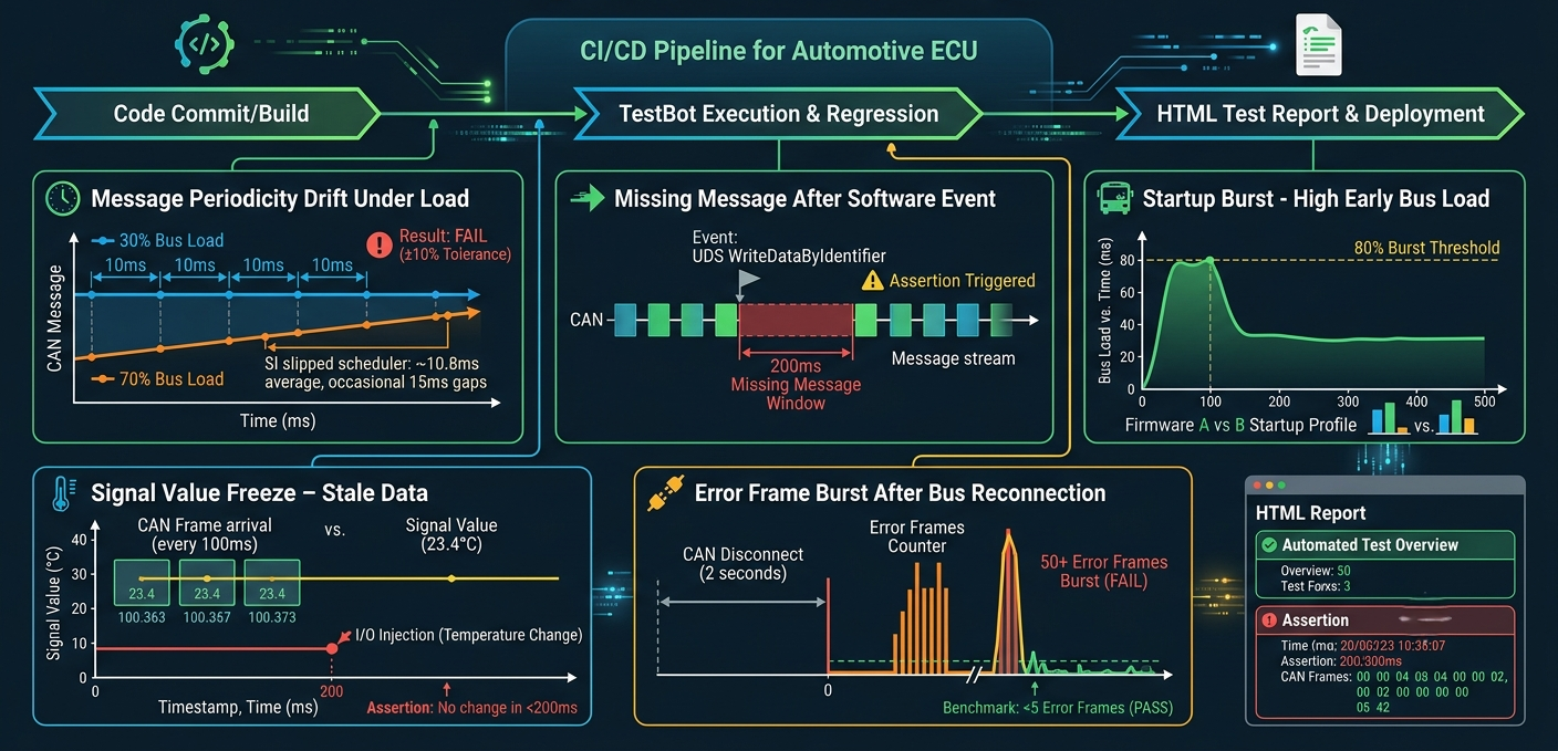
The pattern is familiar to every automotive ECU engineer: the ECU passes all functional tests on the bench. Signal values are correct. DIDs read back correctly. The UDS session works perfectly. Then the vehicle integration lab reports an intermittent CAN communication error on one message, at high bus load, after 40 minutes of operation.
Timing failures are the last class of CAN bugs that stay manual because they are the hardest to reproduce deliberately. They only appear under specific conditions - high bus load, specific temperature, a particular sequence of software events - and they do not show up in a 30-second functional test.
Here are the five most common ones, and how to catch them automatically.
1. Message Periodicity Drift Under Load
A cyclic CAN message should arrive every 10ms. Under nominal bus load (30%), it does. Under 70% bus load - typical in a fully populated vehicle network - the scheduler slips and that same message arrives every 10.8ms on average, with occasional 15ms gaps.
This is a real defect. AUTOSAR COM specifications define message cycle time tolerances - typically ±10% for most messages, tighter for safety-relevant ones. An ECU that drifts outside this tolerance in a loaded network is non-compliant.
Automated test: Run the CAN Monitor agent across a 60-second test window at simulated 70% bus load (generated by the CAN Send agent transmitting background traffic). Assert that every message arrival falls within the ±10% window. Any violation is flagged in the HTML report with the exact timestamp and deviation.
2. Missing Message After Software Event
The ECU stops transmitting a CAN message when a specific software state is entered - not because of a DBC change, but because a software flag is set and the transmission task exits early. It resumes when the state exits. The window is 200ms. Long enough to cause a fault in dependent ECUs, short enough that a human watching CANalyzer at 5 frames/second misses it entirely.
Automated test: Use the CAN Monitor block with a maximum inter-frame gap assertion. Set the threshold to 3× the nominal cycle time (e.g. 30ms for a 10ms message). Trigger the software state via UDS ControlDTCSetting or WriteDataByIdentifier. The missing-message gap is captured instantly and logged with the exact timestamp relative to the state-change trigger.
3. Startup Burst - Too Many Frames in the First 500ms
After a cold start, the ECU transmits all its messages at maximum rate for the first 500ms before settling into its normal schedule. This is a known pattern in some ECU implementations - it satisfies the "first valid frame within Xms" requirement by sending bursts. The downstream effect: a bus load spike that can cause error frames on slower nodes still initialising.
Automated test: Measure bus load during the first 500ms of operation using the CAN Monitor block. Assert the 100ms peak bus load does not exceed the specified burst threshold (typically 80% for 100ms windows even if nominal is 40%). Compare the startup profile across firmware versions to catch regressions in the initialisation sequence.
4. Signal Value Freeze - Correct Value, Wrong Timestamp
A temperature sensor signal reads 23.4°C. Correct value. But it has not updated in 800ms on a message with a 100ms cycle time. The message is transmitting - the frame arrives every 100ms - but the signal value inside it is frozen. The ECU's sensor driver has stopped updating the transmit buffer. The value is stale, but nothing in the message format indicates it.
Automated test: Monitor the signal value over a 5-second window. Inject a known temperature change via the I/O Module Agent (change the NTC resistance via the DRB Agent). Assert the signal value changes within 200ms of the stimulus. A frozen signal that does not respond to stimulus fails the assertion even if the frame itself is arriving correctly.
5. Error Frame Burst After Bus Reconnection
The CAN bus is disconnected and reconnected - a cable pull in the test lab. The ECU enters error-passive state. When reconnected, it should resume normal operation within 128+128 error delimiters. Some ECU implementations send a burst of error frames during recovery that pushes all other nodes into bus-off. A single node's bug takes down the entire network.
Automated test: Use the CAN Monitor's error frame counter. Disconnect the bus via the I/O Module Agent (relay-controlled CAN termination is a standard test jig design). Reconnect after 2 seconds. Assert that total error frames during recovery are below a threshold (typically 5 error frames is acceptable; 50 is not), and that all nodes resume normal operation within 500ms.
Why These Only Appear at 3am
Each of these failures shares a property: they are statistical. They do not fail on every run. They fail under specific conditions - high bus load, long run time, specific state transitions - that are hard to reproduce in a 30-second manual test session but reliably appear in a 60-minute automated regression run.
Running these as part of your nightly CI/CD pipeline, triggered on every firmware build, catches the regression when it is introduced - not when the vehicle integration lab finds it three weeks later. The HTML report shows the exact message, the exact timestamp, and the exact deviation. Root cause analysis takes minutes, not days.
The total setup time for all five tests in TestBot is under two hours. The time you save on the first regression you catch pays for the entire investment.
Read the Full Guide + See the Agent
CAN Bus Testing Guide - Timing, Signals, Fault Injection
The complete CAN bus testing reference: DBC-based signal validation, timing assertions, fault injection, bus load testing, and CI/CD integration - with the CAN/CAN FD Agent.